
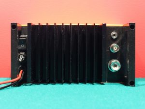
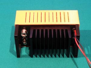
Aufbauend auf einem günstigen Bausatz, führt die Dokumentation Schritt für Schritt über passende Tiefpassfilter und einem maßgeschneiderten, 3D druckbaren Gehäuse zu einem praxistauglichen Fertiggerät. Insgesamt findet man mit Bauteilkosten von knapp 50 € das Auslangen und kann das Gerät nach Vorliegen von Bausatz, Platine für Tiefpassfilter, sonstigen Bauteilen und gedrucktem Gehäuse in rund 6 bis 8 Arbeitsstunden fertigstellen.
Die wesentlichen Leistungsdaten im Überblick:
- Versorgung 12 – 14 V DC (max. ca. 8 A)
- Optimale Eingangsleistung 2 bis 2,5 W
- Ausgangsleistung 30 bis 50 W
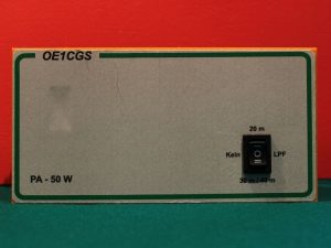
- Optimiert für Betrieb von 40 m bis 20 m
- Manuelle Bandumschaltung
- Ausreichende Unterdrückung von Oberwellen
- Effizienz ≈ 45%
- Passive Kühlung, vorbereitet für Ventilator
There is also an English version available, which contains all necesarry information for building the PA, but should nevertheless be read in conjunction with the document above:
Weitere Informationen und Dateien, wie z. B. Messdaten, Materialliste, Bohrschablone etc. sind auf der Seite Downloads verfügbar.
Das Gehäuse kann von https://www.thingiverse.com/thing:2768290 heruntergeladen werden.
Many thanks for the very carful description. I used the IRF530 based amplifier sucessfully for quite a while and for many SSB QSOs. I found it to be fairly stable if used with a fan and with output power not exceeding 50W. The thermal stability seems to be a bit improved if thin mica pads instead of the silicon pads in the kit are used.
I can highly recommend the 100W version of the kit. Here a MRF9120 is used and the 22Ohm gate to gate resistor is part of the kit. I use it with an overall (both FET) quiescent current of 1A (obtained with 3.4V bias) and for 2.5W input I get 50W output on all bands (I’m not using more). The FET seems thermally very relaxed and input SWR is perfect on all bands tested. The PCB is identical to the one used with the IRF530. Apart from the 22Ohm resistor the only difference seems to be that the input choke has only one turn.
Thanks again and have fun experimenting,
Rudi, DK1CC
Thank you Rudi for your comment. I (thermally) killed some IRF530s on the way and agree, that this version is a bit difficult to run stable. On another model I am running a MRF186 and this is much easier to handle: no thermal issues, less sensitivity to SWR mismatch and (with a minor update on the PCB) the ability to run with a higher supply voltage. Accordingly, I achieve a stable 70 W output on 22 V supply without using a fan. However, I set the bias lower (about 0.2 A, so closer to B mode than A/B). The MRF186 has a gain of about 10dB only, so I have to drive the PA harder. I intend to do try the MRF9120 also, as this one should have a higher gain.
Chris, OE1CGS
Hallo Christoph,
vielen Dank für die Vorstellung dieses tollen Projekts! Die Komponenten sind bestellt und ich bin schon gespannt auf den Aufbau und Abgleich!
73, Roman – DL3TU
Thanks for the information Christoph and Thomas
Where did you buy those MRF186 transistors? I’ve been searching and it seems not easy to buy them reliably.
73, Cesc
EA3IGT.
Thanks for those notes. Especially for providing a good value for the added R6 resistor. I am testing my amplifier now. On 7 MHz I get 45 W with 1 W input. On 14 MHz, it’s 16 W output.
I have blown one IRF530. I suspect it’s thermal issues. I have a large heat sink and believe I have good mounting, but I’m not totally sure. Your suggestion of keeping power down to 30 W or so, and keeping the duty cycle short sounds like a good one. 73- Nick, WA5BDU
Thx and good to hear about your success! 45 W on 40 m looks like a very good gain to me, however 16 W on 20 m seems to be on the low side. I don’t want you to blow another IRF530, but did you ever check with a drive of 2.5 W? Thats what I frequently do with mine and achieve in excess of 30 W out.
It might be of interest to you that right now I am in the process of building another kit, but this time I will use a MRF186 as power MOSFET (see Annex C in my description). Unfortunately I have to fiddle around again with R6 as well as the feedback resistors and possibly some capacity to achieve a better impedance on the output side. However I am hoping to achieve even higher power out without any thermal issues. 73, Chris, OE1CGS
Love you site! Wish I could speak German so I would be sure not to miss anything.
I believe the MRF186 is the key! Not only is it able to handle more power/frequency but the fact that it is case ground enables a direct connection to the heat sink. I think most of the limitation of TO-220 packages is the thermal gasket and smaller mounting screw required. I was surprised to see that the pcb appears to be designed around the MRF186 and the IRF530 added as an after thought.
Do you have an update on any values that may need to be changed? (I would think the power supply should also be cranked up a few volts.)
I understand the MRF186 is several time more expensive but to get more power and more stability seems to be worth to price of a couple coffees.
Thanks
Tom
VA7TQB
Tom, I very much agree with your comment. Actually the one version of this amplifier, which I use on my day to day operations, has the MRF186 in place. I did replace R4 and R5 with 100 Ohm, but this is not a must. R6 stays at 22 Ohm. No other adjustments necessary.
Indeed, it is especaially the superior heat transfer, which makes this version much more reliable. In contrast to a couple of IRF530 replacements, this is still my first MRF186, after several months of operation. In addition, the spectral purity is better. You can (and I do) operate the amplifier up to 16V supply. The limit is imposed by the relais. With small modifications (hint: include a 7812), you could even go higher.
There is one drawback by using the MRF186, though. The gain (about 10dB) is less than with the IRF530. Up to a certain extent, this can be compensated by driving the amplifier with 5W, instead of 2W.
Recently, I started experimenting with the MRF9120. This promises about 6dB more of gain. However, I am not there, yet.
Vy 73,
Chris, OE1CGS
Chris:
Great news!
Wondering how you arrived at the new R values?
I have seen a technique of soldering the module to a copper heat spreader. This was for a 1000W design, so I don’t think it would add much advantage at this level. The surface area is already much more than individual packages.
I notice that with this package the unit is “rated” as 100W. Have you tried it anywhere near that? (Not sure if the relay could handle it? Although it may be that the timing is such that it only carries the power and does not make/break when RF is present)
Actually the 10dB gain may work out well as I was anticipating needing to turn down the power of the driving radio. Less gain may be a direct match.
Are you hinting that, with a clean input signal, the output may not need any extra filtering?
Truly do appreciate all you have done on this. (I may have to use Google translate to read all the gems I feel I am may be missing)
Tom
VA7TQB
Tom,
I simply saw R values of 100 Ohm on pictures of other kits/products, similar to this kit. And I just tried it out. Both (150 and 100 Ohm) are ok for me.
Concerning the heatsink, I totally agree and do not see any reason to go beyond fastening the MRF186 directly to the heatsink.
If 10dB of gain are good for you, absolutely go for this solution. I’ve done several hundred FT8 QSO’s and couple of SSBs with that (5W in) and the amplifier still works like a charm.
No, I am definitely not hinting at using the amplifier without LPF. Maybe you could consider using a 5 element Chebycheff instead of 7 elements like I do, but this is up to you.
Don’t hesitate to contact me on my site, although it might take a few days until I answer.
Cheers,
Chris, OE1CGS
Hallo Christian
Ich habe die Filterplatinen im Toner-Transfermethode mit deinen Unterlagen hergestellt, besten Dank dafür.
Man muss nur bedenken, dass die PDF Vorlagen gespiegelt werden müssen, sonst klappt die Ansteuerung der vorgeschlagenen Relais nicht, da diese +12V am Pin 1 benötigen.
72 de DC9LW
Hallo HG,
danke für den Hinweis! Ich habe die Unterlagen ausgetauscht.
Jetzt kann man sie direkt verwenden, ohne Spiegelung.
73 de OE1CGS
Hallo Christoph,
habe versucht für die Drossel L1 den Kupferlackdraht aus dem Bausatz zu verwenden. Leider habe ich dabei die Isolierung verletzt. So werde ich, wie du , auch isoliertes alternatives Material nehmen. Deine Bohrschablone passte bei mir nicht, (fehlerhafte Druckeinstellung ?) , sonst alles ok, eine gute Beschreibung. Ein Gehäuse habe ich schon gedruckt . Vielen Dank für die Vorlage auf thingiverse.
Uwe df9yw
Ja, empfehle generell für die Drossel gleich zu einem isolierten Draht aus der Bastelkiste zu greifen. Beim Ausdruck der Bohrschablone unbedingt darauf achten in den Druckeinstellungen „Tatsächliche Größe“ auszuwählen und nicht das (meistens voreingestellte) „Anpassen“. Dann sollte es auch funktionieren. Chris, OE1CGS
Mein Bausatz ist gerade angekommen; vielen Dank für Deine ausführliche Beschreibung!
73 de DM1CR
Gerne! Würde mich freuen zu hören, ob der Zusammenbau auch gut klappt. Natürlich auch, ob und wo ich die Beschreibung noch verbessern kann. Chris, OE1CGS